

UART, RS485 and CAN refer to different parts of a field-communication design. A header signal may require a transceiver, termination or isolation before it reaches equipment. Check the complete ArmSoM board or carrier circuit before connecting a bus.
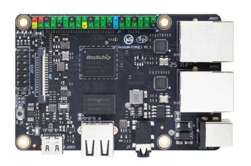
ArmSoM Forge1
Identify the electrical layer
For UART, confirm logic levels and signal direction. For RS485 or CAN, identify the transceiver, connector pinout, termination and grounding arrangement. Review protection and isolation requirements for the installation. Software can configure a controller, but it cannot correct an incompatible electrical connection.
Review the installation as a circuit
Record signal levels, grounding, termination, cable length and isolation requirements. Industrial equipment can introduce ground differences and electrical noise. Confirm whether protection or isolation is already present or must be added. For CM1, distinguish the module pins from CM1-IO connections; for Forge1 and Sige3, use their own connector definitions.
Validate communication without controlling machinery
Begin with a safe bench device or simulator and a known message pattern. Confirm baud rate, framing, bus timing and direction control. For CAN, inspect link state and error counters. For RS-485, verify turnaround behavior. Only move to live equipment after the electrical design and application commands have been reviewed.
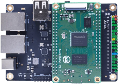
ArmSoM CM1-IO carrier and module. Carrier connectors and power input are distinct from the bare CM1 module.
Match the choice to your requirements
Requirement or situation | What to evaluate | Decision detail |
UART | Logic-level serial | Verify voltage and framing. |
RS-485 | Differential physical bus | Check transceiver, direction and termination. |
CAN | Controller plus physical bus | Check bitrate, termination and error handling. |
Example design
A UART signal is not a complete RS485 or CAN connection
A processor interface often needs external transceivers, termination and protection before it can connect to field equipment. Work from the complete circuit and bus specification. Test the intended cable and connected devices, including their reference-ground arrangement. Looping a short wire on a desk can confirm basic communication but cannot establish reliable operation in a noisy installation.
Hardware and documentation
CM1 · RK3506J
RK3506J with three Cortex-A7 cores, a Cortex-M0 and 256 MB / 512 MB DDR3L options. The 5 V module supply differs from the CM1-IO carrier’s 12 V input.
Hardware documentation · Product details
Forge1 · RK3506J
RK3506J development board with 512 MB DDR3L, NAND storage and dual 100 Mbps Ethernet. Check the complete interface circuit before field wiring.
Hardware documentation · Product details
Sige3 · RK3568B2
RK3568B2 with a 2.5GbE port and a separate Gigabit Ethernet port. Consult the revision-specific manual for expansion and boot support.
Hardware documentation · Product details
Frequently asked questions
Can two pins labeled TX and RX connect directly to RS-485?
Not unless the documented interface already includes the appropriate physical-layer hardware.
Product information and support
Sources
Written by ArmSoM using the documentation below. Example designs are proposals, not measured customer installations.