

A compute-module kiosk puts display, touch, storage and power decisions onto the carrier design. CM5 may suit that approach when its documented interfaces meet the terminal’s needs. The enclosure and maintenance procedure should be part of the design from the start.
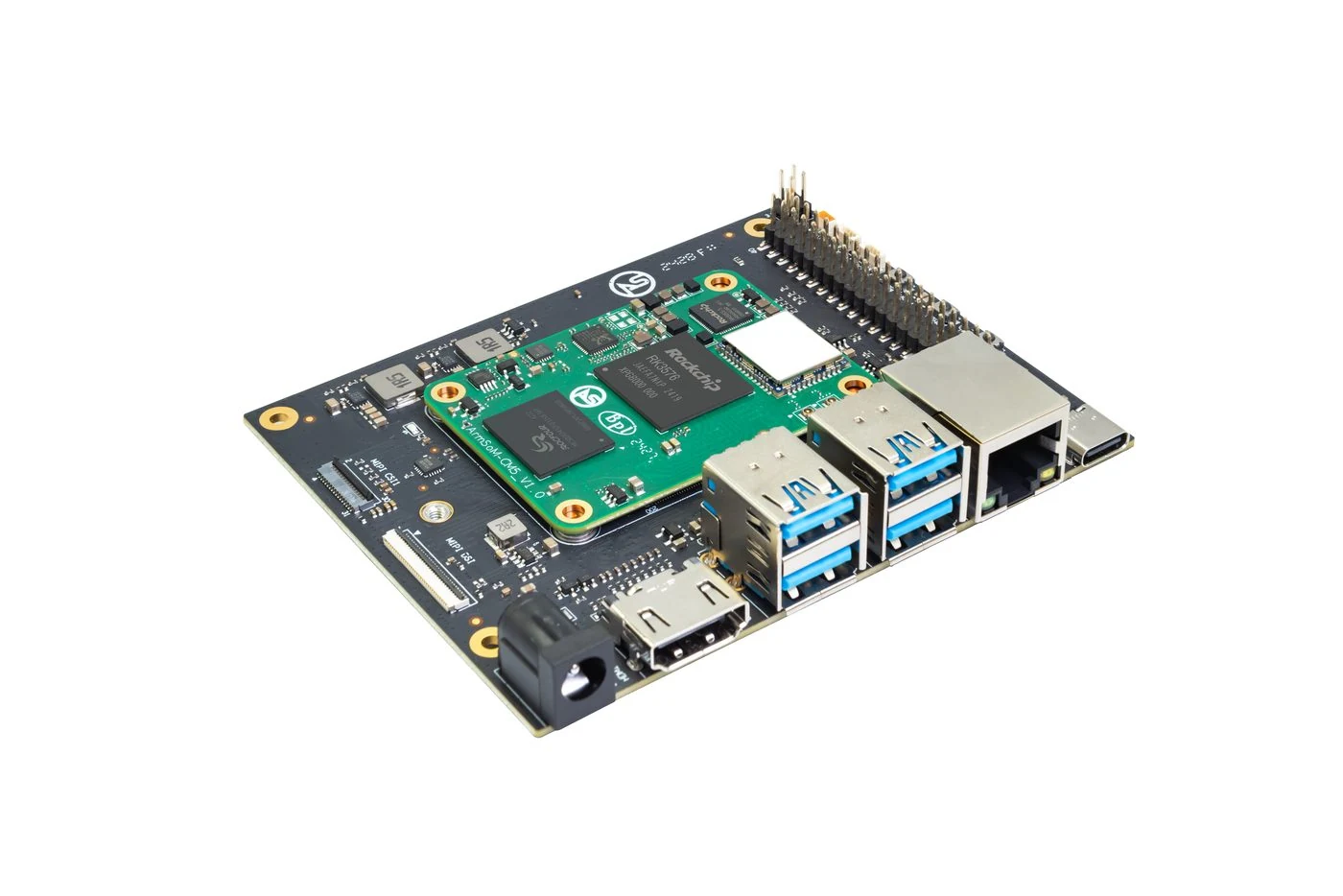
ArmSoM CM5 evaluation carrier and module.
Design for service access
Locate the storage, debug connection and recovery controls where a technician can reach them. Check the display and touch interfaces against the carrier routing and image support. Include cable clearance and cooling in the enclosure review. A prototype that works with the lid open may still be difficult to maintain once installed.
Match the user interface to the platform
A lightweight status interface has different needs from a browser with complex animation and video. Measure startup, interaction response and memory on the intended image. CM1’s industrial Linux positioning should not be confused with a high-end desktop board; CM5 offers a different CPU and multimedia platform. Avoid selecting only from a module’s physical size.
Design access for the operator
Keep power, storage and recovery connections reachable without dismantling the entire product. Define behavior after an unexpected restart and when backend services are unavailable. Limit the application’s privileges and protect user data. Before production, validate the finished enclosure and carrier rather than only a development kit on a desk.
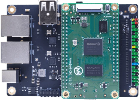
ArmSoM CM1-IO carrier and module. Carrier connectors and power input are distinct from the bare CM1 module.
Match the choice to your requirements
Requirement or situation | What to evaluate | Decision detail |
Display | Panel, timing and power | Validate on the carrier. |
Touch | Controller and coordinate mapping | Test all orientations. |
Service | Recovery and data handling | Plan field maintenance. |
Example design
Keep kiosk servicing possible after installation
A compute module inside a kiosk still needs accessible recovery, diagnostics and replacement procedures. Plan a service connector or removable panel before the enclosure is finalized. Test display and touch with the intended operating-system image, then document which settings belong to the carrier and which belong to the application. Replacing a module should not require rediscovering its entire software configuration.
Hardware and documentation
CM5 · RK3576
RK3576 module, 6 TOPS NPU, 55 × 40 mm and two 100-pin connectors. Module supply: 4 V recommended, 5.5 V maximum. The planned v2.0 memory option is LPDDR4/4x; current availability must be confirmed.
Hardware documentation · Product details
CM1 · RK3506J
RK3506J with three Cortex-A7 cores, a Cortex-M0 and 256 MB / 512 MB DDR3L options. The 5 V module supply differs from the CM1-IO carrier’s 12 V input.
Hardware documentation · Product details
Frequently asked questions
Can the same kiosk image run on CM1 and CM5?
Do not assume that. Processor architecture, board support and application dependencies differ.
Product information and support
Sources
Written by ArmSoM using the documentation below. Example designs are proposals, not measured customer installations.