

SPI displays need the correct bus signals, control pins and panel driver. A lit backlight proves little about that connection. Record the exact display controller and test its initialization before integrating the screen into the application.
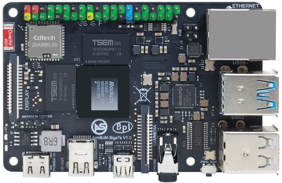
ArmSoM Sige7s
Map data and control signals together
Include chip select, data/command, reset and backlight control as well as clock and data. Check voltage levels and the target board’s pin multiplexing. Use the panel’s supported initialization and timing settings. A generic SPI transfer can succeed even when the display interprets the data incorrectly.
Match the driver to the panel controller
Identify the actual controller and panel initialization sequence. Linux can expose displays through different driver stacks depending on the image. Follow the supported configuration for that kernel rather than copying an overlay file from another SoC. Start at a conservative documented bus speed and verify orientation and color order.
Measure whether the display suits the UI
A small status screen may be acceptable even when animation is limited. Full-screen updates, font rendering and touch latency need a separate evaluation. Test repaint behavior during other application activity and after restart. Report the tested resolution, refresh behavior and driver rather than promising desktop-like graphics from an SPI connector.
Match the choice to your requirements
Requirement or situation | What to evaluate | Decision detail |
Connections | SPI plus control and power pins | Map all functions. |
Driver | Controller and initialization | Use the target kernel’s supported path. |
Experience | Update rate and touch behavior | Test the actual interface. |
Example design
A display controller needs more than an SPI device node
For an SPI display, chip select, reset, data/command control and backlight may all need configuration. Confirm the controller model and panel initialization sequence before assuming an existing example transfers. The Linux device tree must describe the correct hardware. Measure useful refresh behavior with the final application; bus clock alone does not define how quickly a complete screen updates.
Hardware and documentation
Sige5 · RK3576
RK3576, four Cortex-A72 and four Cortex-A53 cores, 6 TOPS NPU, dual Gigabit Ethernet and M.2 PCIe 2.1 x1.
Hardware documentation · Product details
Sige7s · RK3588S
RK3588S, 6 TOPS NPU, Gigabit Ethernet and removable eMMC. Dimensions: 85 × 56 × 17 mm. Disconnect power before replacing eMMC.
Hardware documentation · Product details
Frequently asked questions
Can an SPI screen use a generic HDMI setup?
No. SPI panels use a different connection and driver path.
Product information and support
Sources
Written by ArmSoM using the documentation below. Example designs are proposals, not measured customer installations.