
A PCIe connector tells only part of the expansion story. Lane count, generation, routing and software support determine what a module can use through its carrier. Storage and accelerator designs need those details before the connector footprint is chosen.
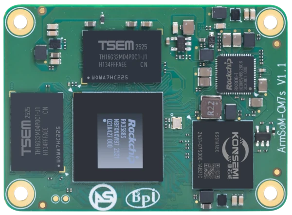
ArmSoM CM7s
Trace the link through the carrier
Follow the processor’s supported PCIe interface through the module pins, carrier routing and connector. Check lane allocation and any shared functions. The slowest negotiated link and the attached device shape the usable bandwidth; an SSD’s advertised speed is not a measurement of the whole path. Verify enumeration and sustained operation on the intended image.
Test the device you intend to ship
Check physical keying, power budget, reset, reference clock and link negotiation. An SSD, network adapter and accelerator create different driver and power demands. Record the negotiated link as well as useful application throughput. If the product requires sustained writes or simultaneous network traffic, test that combination rather than relying on a short standalone storage benchmark.
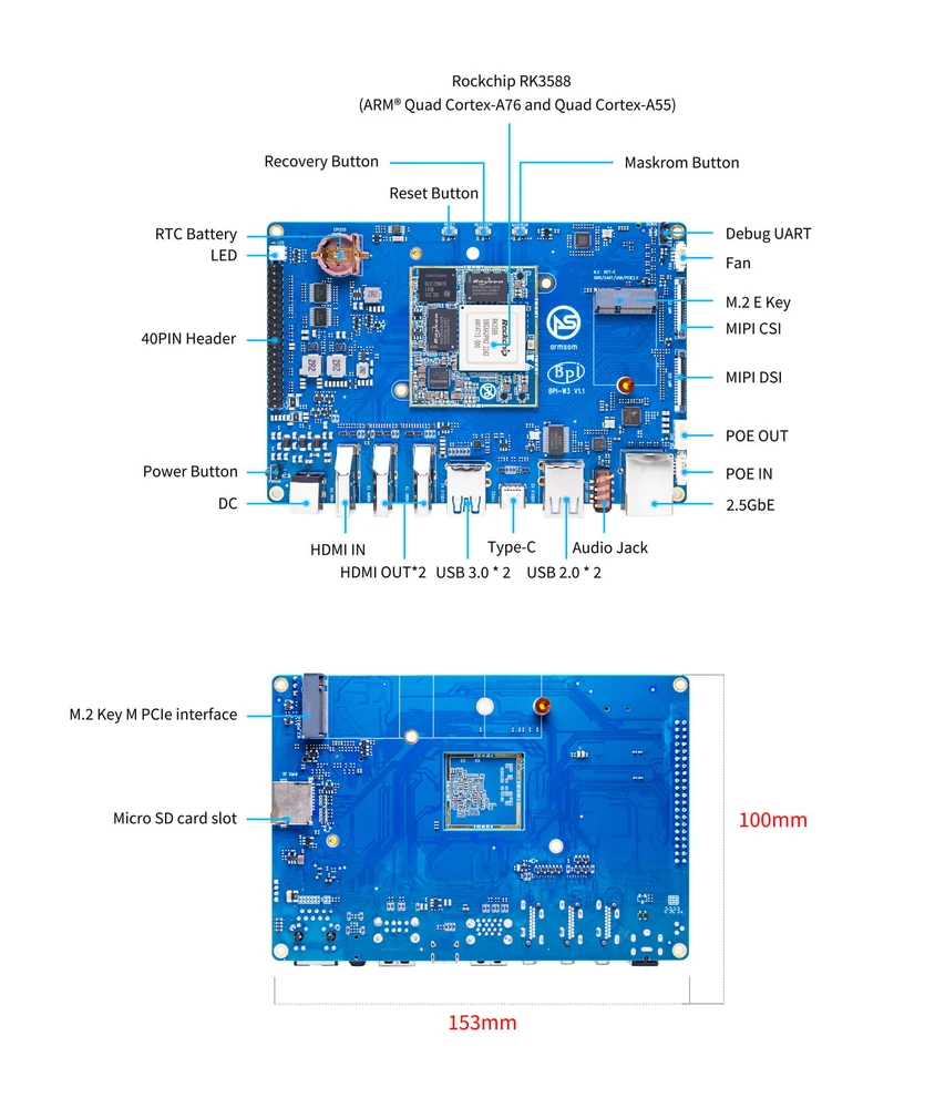
ArmSoM LM7 development kit. The module and carrier have different electrical and mechanical requirements.
Match the choice to your requirements
Requirement or situation | What to evaluate | Decision detail |
Lane count | Module plus carrier routing | Count only the lanes actually connected. |
Shared signals | Selected mux configuration | Do not count mutually exclusive functions twice. |
Peripheral support | Driver, power and link training | Enumeration is not a sustained-load result. |
Example design
Match the peripheral to the complete PCIe path
An M.2 connector identifies a mechanical family, not a promise of a particular PCIe lane count, storage protocol or power capacity. Trace the route through the module, carrier and adapter to the actual peripheral. Record keying, supported device length and signal routing. A device that enumerates successfully still needs sustained traffic and reset testing. For storage, test reads and writes separately rather than using enumeration as evidence of useful throughput.
Hardware and documentation
CM5 · RK3576
RK3576 module, 6 TOPS NPU, 55 × 40 mm and two 100-pin connectors. Module supply: 4 V recommended, 5.5 V maximum. The planned v2.0 memory option is LPDDR4/4x; current availability must be confirmed.
Hardware documentation · Product details
CM7s · RK3588S
RK3588S, 6 TOPS NPU, 55 × 40 mm and three 100-pin connectors. ArmSoM offers CM7s as an Orange Pi CM5 replacement option; confirm the exact carrier, revision and software combination.
Hardware documentation · Product details
LM7 · RK3588
RK3588 in an LGA506 module format. Module input: 4 V ±5%. Follow the module power requirements separately from a development carrier’s external input.
Hardware documentation · Product details
Frequently asked questions
Does an M.2 socket always mean NVMe support?
No. Keying and electrical routing must match the device and protocol.
Product information and support
Sources
Written by ArmSoM using the documentation below. Example designs are proposals, not measured customer installations.