

Camera and display migration is rarely settled by matching ribbon connectors. Sensor drivers, lane routing, control signals and panel timing all matter. A compute-module comparison should name the actual camera and display the product must support.
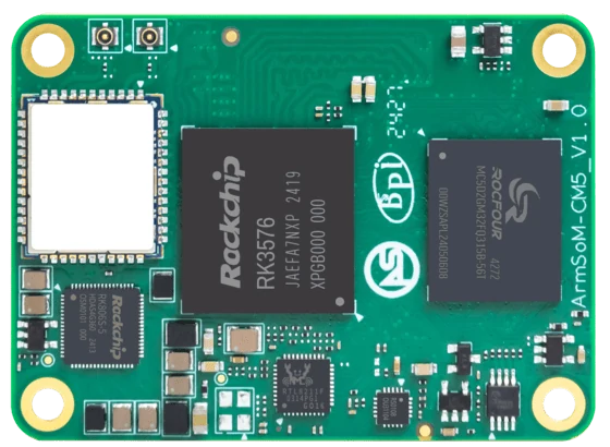
ArmSoM CM5
Write an endpoint list
For each sensor or panel, record the model, electrical interface, lane count and control bus. Check the module and carrier documentation against that list. A supported processor interface may be unrouted or shared on the carrier. Validate each endpoint alone before testing cameras and displays together.
Validate capture and display together
First confirm one camera mode and one panel mode independently. Then run the intended capture, processing and display pipeline and watch for bandwidth, format and clocking problems. Save the device-tree and image version with the result. If your existing Raspberry Pi design uses two outputs, verify each target path explicitly instead of inferring equivalent dual-output support.
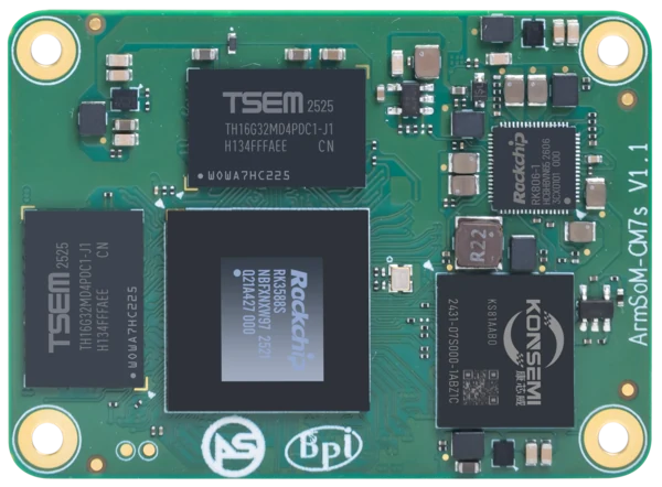
ArmSoM CM7s
Match the choice to your requirements
Requirement or situation | What to evaluate | Decision detail |
Camera | Sensor, lanes and control bus | Verify a real capture at the required mode. |
Display | Panel timing and power | Verify cold boot, rotation and reconnect as applicable. |
Combined system | Concurrent data paths | Measure dropped frames and sustained stability. |
Example design
Name the panel and sensor
A carrier requirement such as “MIPI camera” is too broad for procurement. Specify the sensor, lane arrangement, connector pinout and driver. Do the same for the display panel, including resolution, timing, touch interface and backlight control. Then check simultaneous use: a camera can work alone while combined capture and display expose memory or driver limitations. Save a known-good image for the exact assembly.
Hardware and documentation
CM5 · RK3576
RK3576 module, 6 TOPS NPU, 55 × 40 mm and two 100-pin connectors. Module supply: 4 V recommended, 5.5 V maximum. The planned v2.0 memory option is LPDDR4/4x; current availability must be confirmed.
Hardware documentation · Product details
CM7s · RK3588S
RK3588S, 6 TOPS NPU, 55 × 40 mm and three 100-pin connectors. ArmSoM offers CM7s as an Orange Pi CM5 replacement option; confirm the exact carrier, revision and software combination.
Hardware documentation · Product details
Frequently asked questions
Can a passive ribbon adapter guarantee compatibility?
No. Electrical signalling and software support must also match.
Product information and support
Sources
Written by ArmSoM using the documentation below. Example designs are proposals, not measured customer installations.