

ArmSoM CM5’s documented module input recommends 4 V, with 5.5 V listed as the maximum. Those values need checking against a CM4 carrier’s actual regulated output. The voltage printed beside the carrier’s external connector is not the module supply specification.
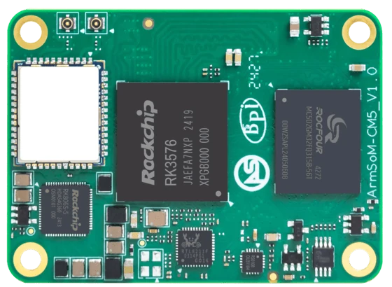
ArmSoM CM5
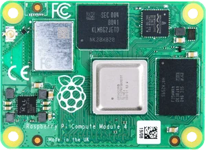
Raspberry Pi Compute Module 4 Photo: Raspberry Pi
Images identify the boards and are not to physical scale. Pictured configurations and included accessories may differ.
Measure at the module rail
Review the regulator, startup sequence and available current using the carrier schematic or released PDF. During validation, measure the module rail through startup and representative load changes. Inspect connected peripherals for back-power paths when the module is off. Keep the exact carrier and CM5 revision in the power-validation record.
Test startup and worst-case load
After review, measure startup behaviour, module voltage and peripheral supply stability under the actual load. Camera startup and storage activity can create different demands from an idle desktop. Check repeated cold starts, controlled shutdown and recovery after a supply interruption. Keep the test within component ratings and record the supply, cable and carrier revision with the result.
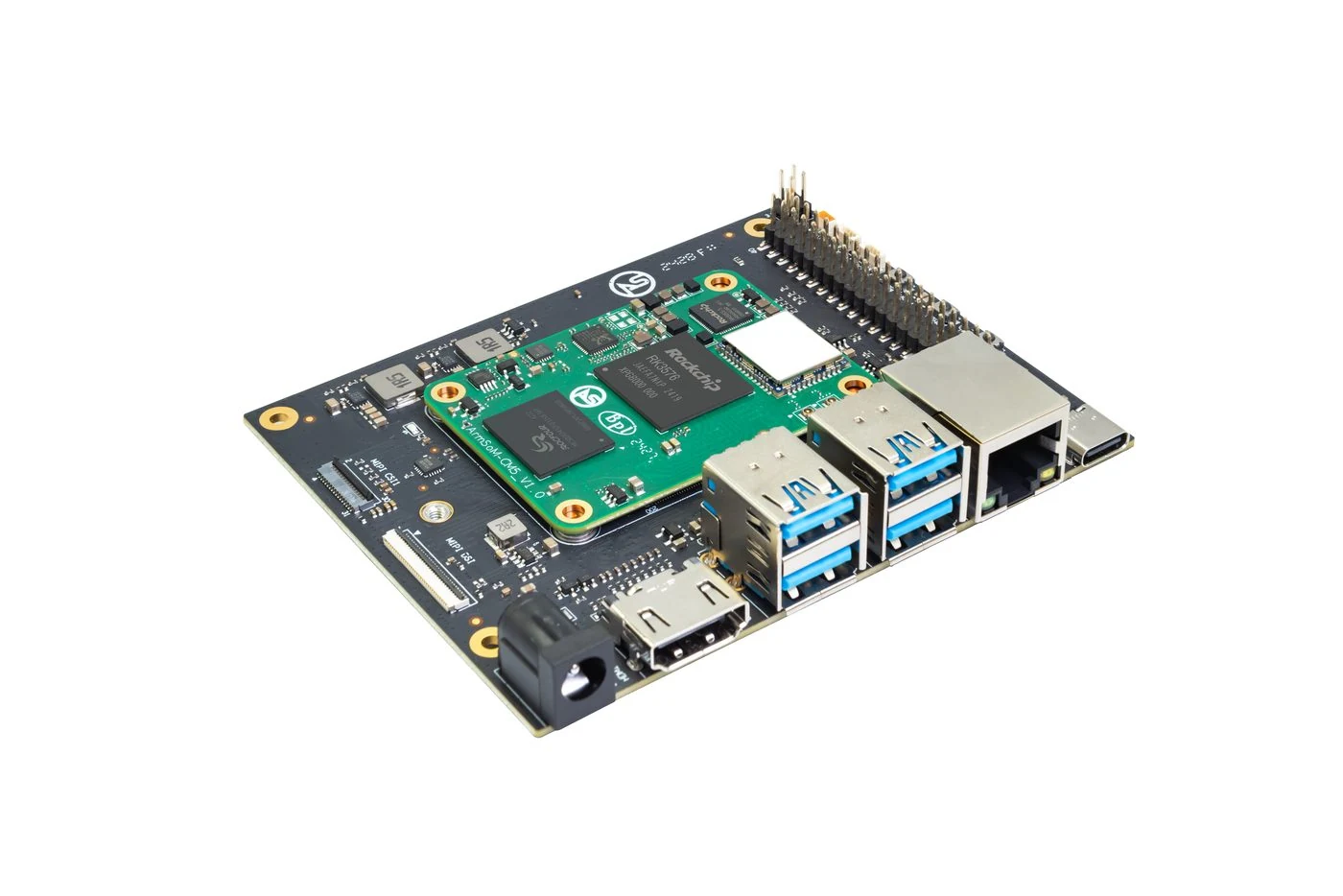
ArmSoM CM5 evaluation carrier and module.
Match the choice to your requirements
Requirement or situation | What to evaluate | Decision detail |
Carrier input | External supply connection | Do not confuse it with the module rail. |
Module power | Voltage and sequencing | Resolve discrepancies before first power-on. |
Peripherals | Peak load and back-power paths | Measure the finished configuration. |
Example design
Check the supply at the module
A carrier input label describes where power enters the carrier, not necessarily the voltage delivered to every module rail. Compare the regulator outputs and sequencing with the CM5 electrical specification. Measure startup with the intended peripherals connected. A system that boots from a bench supply can fail with a long cable or a different regulator response. Keep module input requirements distinct from a development board’s convenient external connector.
Hardware and documentation
CM5 · RK3576
RK3576 module, 6 TOPS NPU, 55 × 40 mm and two 100-pin connectors. Module supply: 4 V recommended, 5.5 V maximum. The planned v2.0 memory option is LPDDR4/4x; current availability must be confirmed.
Hardware documentation · Product details
Frequently asked questions
Can I use the same power supply because the connectors fit?
Only after confirming the carrier regulation and module requirements; connector fit is not electrical approval.
Product information and support
Sources
Written by ArmSoM using the documentation below. Example designs are proposals, not measured customer installations.