

A CM4 carrier can look compatible with ArmSoM CM5 and still need electrical or software changes. The compatibility record should identify the exact carrier, module revision and interfaces tested. This article sets out that record; it does not certify every CM4 carrier.
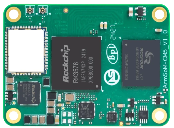
ArmSoM CM5
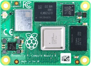
Raspberry Pi Compute Module 4 Photo: Raspberry Pi
Images identify the boards and are not to physical scale. Pictured configurations and included accessories may differ.
Review the wiring before the boot test
Compare power rails, grounds, reset, boot control and reserved pins using the released documents. CM5 recommends 4 V at the module and specifies a 5.5 V maximum. Check how the carrier produces that rail and whether connected signals can back-power the module. Resolve these questions before attempting a powered trial.
Build a test matrix around actual use
Record module and carrier revisions, image checksum, storage and every connected peripheral. Test boot, Ethernet, USB, display, camera, audio and any expansion separately, then run the combined application. Add repeated cold starts and recovery tests. Mark unused interfaces as not tested rather than pass. The published CM5 revision notes, including the v1.2 pin-21 issue, belong beside the result.
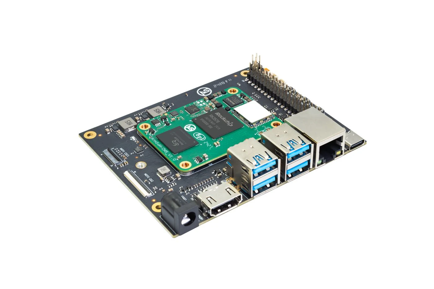
ArmSoM CM5 evaluation carrier and module.
Match the choice to your requirements
Requirement or situation | What to evaluate | Decision detail |
Electrical review | PDF pinout comparison | No unexplained supply or reserved-pin conflicts. |
Functional checks | Named peripheral on named image | Pass, limitation or not tested for each interface. |
Combined operation | Real application and repeated starts | No inference from one successful desktop boot. |
Example design
Create a compatibility matrix before first power
For each carrier function, record the source pin, destination pin, voltage domain and expected behavior. Include pins that the original design tied high, tied low or left unconnected. Review reset and boot selection as carefully as data interfaces. Only after the electrical review should a controlled bring-up begin. A boot success can be one row in the matrix; it cannot replace the remaining camera, display, storage and power checks.
Hardware and documentation
CM5 · RK3576
RK3576 module, 6 TOPS NPU, 55 × 40 mm and two 100-pin connectors. Module supply: 4 V recommended, 5.5 V maximum. The planned v2.0 memory option is LPDDR4/4x; current availability must be confirmed.
Hardware documentation · Product details
Frequently asked questions
Can one successful carrier test prove universal CM4 compatibility?
No. It validates only the documented combination and tested functions.
Product information and support
Sources
Written by ArmSoM using the documentation below. Example designs are proposals, not measured customer installations.