
CM5, CM7s, LM7 and AIM7 use different processors, connectors and integration approaches. Their common purpose as modules does not make them carrier-compatible. Start with the product’s mechanical and electrical architecture, then narrow the processor and memory choices.
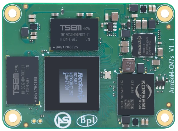
ArmSoM CM7s
Choose the integration format
CM5 and CM7s use board-to-board connectors, AIM7 uses a 260-pin SO-DIMM connector, and LM7 uses an LGA506 package. These choices affect carrier layout, assembly and service access. Compare released mechanical drawings and pinouts for the chosen module. Keep the development kit’s power and connectors separate from the bare module specification.
Check power before evaluating a carrier
The documented CM5 module supply is 4V recommended with a stated maximum of 5.5V. CM7s and AIM7 have their own 5V requirements. LM7 specifies 4V ±5%. Development-kit inputs can differ from the module rail. Treat these as separate circuits and use the released hardware documentation for the exact revision.
Match productization work to the team
A development carrier speeds early software evaluation. A custom carrier adds routing, power, mechanical and manufacturing work. LGA integration introduces assembly and rework considerations distinct from a socketed module. Include provisioning, test access and servicing in the choice, not only CPU and memory. Obtain a confirmed configuration and supply plan before committing a production design.
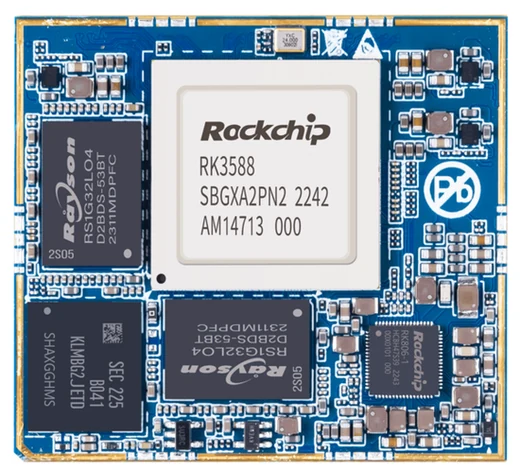
ArmSoM LM7
Match the choice to your requirements
Requirement or situation | What to evaluate | Decision detail |
CM5 | RK3576; two 100-pin connectors | Review CM4-related compatibility details and supply. |
CM7s | RK3588S; three 100-pin connectors | Validate the intended carrier and revision. |
AIM7 | RK3588; 260-pin SO-DIMM | Use a documented carrier/image combination. |
LM7 | RK3588; 506-pin LGA | Plan PCB integration, assembly and 4V supply. |
Example design
Choose the module family before drawing a carrier
CM5, CM7s, LM7 and AIM7 represent different processors, connector or package formats and integration paths. Begin with mechanical constraints, required interfaces and assembly capability. A socketed module and an LGA module impose different manufacturing and service decisions. Do not select from headline NPU capability alone; power, boot access and software support belong in the first design review.
Hardware and documentation
CM5 · RK3576
RK3576 module, 6 TOPS NPU, 55 × 40 mm and two 100-pin connectors. Module supply: 4 V recommended, 5.5 V maximum. The planned v2.0 memory option is LPDDR4/4x; current availability must be confirmed.
Hardware documentation · Product details
CM7s · RK3588S
RK3588S, 6 TOPS NPU, 55 × 40 mm and three 100-pin connectors. ArmSoM offers CM7s as an Orange Pi CM5 replacement option; confirm the exact carrier, revision and software combination.
Hardware documentation · Product details
LM7 · RK3588
RK3588 in an LGA506 module format. Module input: 4 V ±5%. Follow the module power requirements separately from a development carrier’s external input.
Hardware documentation · Product details
AIM7 · RK3588
RK3588 module with a 6 TOPS NPU and 260-pin SO-DIMM connector. ArmSoM has tested a Jetson Nano B01 carrier; this does not establish compatibility with all Jetson carriers or NVIDIA software.
Hardware documentation · Product details
Frequently asked questions
Can a module be chosen by dimensions alone?
No. Connector signals, power, mechanical clearance and software must also fit.
Does a development-kit power adapter connect directly to its bare module?
Not necessarily. The carrier may regulate a different input voltage.
Product information and support
Sources
Written by ArmSoM using the documentation below. Example designs are proposals, not measured customer installations.