

Moving a Raspberry Pi Compute Module 5 (CM5) product to ArmSoM CM7s starts with the carrier requirements. Both modules have a 55 × 40mm footprint, but CM7s uses three 100-pin board-to-board connectors and Raspberry Pi CM5 uses two. A shared outline does not establish pin compatibility or make an existing carrier safe to reuse.
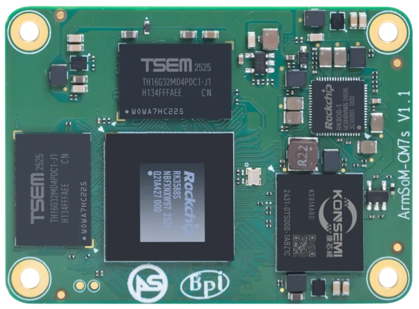
ArmSoM CM7s v1.1. Photograph: ArmSoM product media. Confirm the revision of the supplied module.
The useful question is which parts of the product can remain: the enclosure, external connectors, application behavior and peripheral devices may still be suitable. The carrier's connections to the module must be checked against the exact CM7s hardware revision. CM7s hardware documentation; Raspberry Pi CM5 connector reference.
Turn the old carrier into a requirements list
Begin with what the finished product needs. Record each external connection, its electrical interface, required throughput and software dependency. A connector labelled “camera” is not enough: the sensor, lane arrangement, control bus, clock and power requirements all affect the design.
Include service features that are easy to omit from the block diagram. Manufacturing programming, serial debugging, forced recovery, fan control and status indicators may not be customer-facing, but losing them can make a field failure much harder to diagnose.
Example migration worksheet for a custom product
Product requirement | Carrier question | Evidence before layout |
Embedded display | Which CM7s display signal group will drive the panel? | Panel timing, lane count, power sequence and driver path |
Camera input | Do sensor lanes and control signals fit the selected interface? | Sensor datasheet, connector mapping and a working driver |
External storage | Which PCIe or SATA group is allocated? | Lane allocation, device power and software validation |
Service USB | Is the intended host or device function available? | Port role, routing and a tested recovery process |
Field I/O | What voltage levels and external transceivers are required? | Electrical limits and interface-specific circuitry |
Review the complete mechanical stack
Check the module outline, mounting holes, mating connector heights and component keep-outs against the enclosure. Add the heatsink, thermal pad, screws and cable bend space. A design can satisfy the bare PCB dimensions and still fail to assemble once cooling hardware is fitted.
Use a mechanical drawing for the actual revision rather than measuring a marketing photograph. ArmSoM's 1.6mm PCB figure is not a specification for total assembled height. Mixing PCB thickness with another module's total height would give a misleading clearance comparison.
Separate module power from carrier input power
CM7s takes a 5V module supply. The CM7s-IO development carrier is documented with a 12V DC input; its circuitry supplies the module and other loads. The carrier input rating must not be applied directly to the bare module. CM7s and CM7s-IO power specifications.
For a custom carrier, work out the complete load: module, cameras, storage, display circuitry, USB peripherals and cooling. Verify rail sequencing and control signals from the current design documentation. The supply also needs to tolerate startup and workload transitions, not just the average current seen on a lightly loaded desktop.
Measure the module supply at the carrier under the most demanding intended combination of peripherals. Record the input voltage, cable, regulator configuration and cooling conditions alongside the result. That makes a brownout investigation reproducible.
Allocate shared interfaces before routing
The current CM7s interface table identifies several alternatives within shared signal groups. HDMI and eDP share a group. One high-speed expansion group selects SATA III or PCIe 2.1 ×1; another selects SATA III, PCIe 2.1 ×1 or USB 3.0. A separate Type-C/DisplayPort group has its own supported modes. These choices require a carrier and software configuration that agree. CM7s multiplexed interface reference.
Product ports → Signal allocation → Carrier routing → Driver configuration
Design sequence, not a pinout or wiring diagram.
Suppose a product requires an SSD and an additional USB 3 device. Assign both requirements to specific signal resources before selecting the connectors. The existence of a USB socket and a storage slot on a schematic does not prove they can operate concurrently in the selected mode.
Use the RK3588S and CM7s documentation for lane planning. A design example for a different RK3588 module may expose interfaces that this module does not. Similarly, ports added by a USB hub are downstream connections, not additional independent host channels.
Make the hardware revision part of the design record
The CM7s revision note identifies a v1.1 issue on CN2 pins 2 and 4 and describes a correction planned for v1.2. Treat those signals as unavailable on v1.1. Obtain confirmation for the module being supplied before relying on a later correction.
Public references checked on 20 November 2026
Reference and scope | What it establishes | Action for your carrier |
CM7s v1.1 module note | CN2 pins 2 and 4 have a documented issue | Record the module marking and exclude these signals from a v1.1 design unless ArmSoM provides a validated solution |
CM7s v1.2 reference in that note | A planned correction, not evidence of the revision in your shipment | Request the applicable pin definitions and revision confirmation for the ordered module |
The table is checked against the CM7s-IO V1.0 schematic; its numbers identify physical header pins | Use it for that carrier's header. Do not substitute it for the module connector pinout or Linux GPIO line offsets | |
The original module's mechanical and electrical reference | Compare each required signal with the CM7s revision-specific reference; connector count alone cannot supply a pin map |
Keep one design record containing the module marking, carrier revision, reference-document revision, allocated signal groups and image filename. Link every peripheral test to that record. If hardware or software changes during qualification, repeat the affected checks on the new combination.
Bring up one dependency at a time
Start from the module's documented power and recovery path. Establish serial access and reliable booting before adding the application's more demanding peripherals. Then validate storage, networking and the selected display or camera path individually.
Once those functions work separately, run them together in the enclosure. Camera capture plus storage writes plus a busy display can expose power, thermal or bandwidth problems that a sequence of single-interface tests misses. Include repeated cold boots and recovery from interrupted updates in the acceptance criteria.
Carrier migration questions
Can I reuse a Raspberry Pi CM5 IO Board?
Do not assume it supports CM7s. Validate the exact connector geometry, pinout and electrical requirements before connecting a module. A documented CM7s-compatible carrier is the practical starting point for evaluation.
Does a successful first boot validate the carrier?
It proves only that one boot condition worked. Peripheral loading, recovery, sustained workload and enclosure temperature still need qualification.
For a design review, send ArmSoM the required interface list, enclosure constraints and proposed module configuration. Review the module and carrier options, and continue with the Linux application migration guide. If the carrier changes are too extensive, return to the platform selection comparison before committing the design.
Selection guidance based on manufacturer documentation. No comparative hardware benchmark was performed for these articles.