

The right power supply depends on the exact board and its attached devices. A matching connector or a printed wattage is not enough. Use the board’s input requirements, then validate startup and load changes through the chosen cable and regulator.
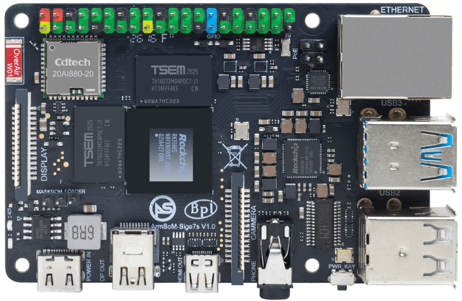
ArmSoM Sige7s
Check voltage at the load
Record the supply model, cable and connected peripherals. Measure the board input during startup and the busiest expected workload, within a suitable test setup. Check for voltage drop, resets and unstable peripherals. Distinguish module input requirements from the external power connector on its development carrier.
Include peripheral transients
Storage startup, wireless transmission and cameras can create demand changes that a simple idle measurement misses. Determine whether peripherals draw from the board or an independently powered hub. Measure at the relevant points without shorting or altering the circuit. A high current rating on an adapter does not compensate for excessive cable voltage drop.
Test for recoverable behavior
Observe boot, simultaneous workload and peripheral reconnect. Review logs for resets, storage errors and device disconnects. Check the final enclosure’s heat and cable routing. Use a suitable protected supply and obtain electrical review for custom power designs. Publish a tested configuration rather than a single wattage said to fit every accessory combination.
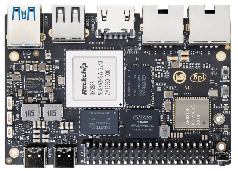
ArmSoM Sige7
Match the choice to your requirements
Requirement or situation | What to evaluate | Decision detail |
Board input | Exact voltage and connector requirements | Use its manual. |
Peripherals | Steady and startup demand | Measure the connected system. |
Distribution | Cable drop and hub power | Check the full path. |
Example design
Check voltage at the board during peak demand
An adapter’s label does not describe voltage after a long cable or connector loss. Exercise the board with its actual storage, radios and USB peripherals while monitoring stability. Confirm the permitted input range from the exact board documentation. A power connector that fits is not proof of the right voltage, polarity or negotiated supply behavior.
Hardware and documentation
Sige7 · RK3588
RK3588, 6 TOPS NPU, dual 2.5GbE and M.2 PCIe 3.0 x4. Check the selected eMMC and wireless configuration.
Hardware documentation · Product details
Sige7s · RK3588S
RK3588S, 6 TOPS NPU, Gigabit Ethernet and removable eMMC. Dimensions: 85 × 56 × 17 mm. Disconnect power before replacing eMMC.
Hardware documentation · Product details
Frequently asked questions
Is a larger adapter current rating always a problem?
The supplied voltage and compatibility must be correct; the system draws current according to its load. Use the board’s documented recommendations.
Product information and support
Sources
Written by ArmSoM using the documentation below. Example designs are proposals, not measured customer installations.