

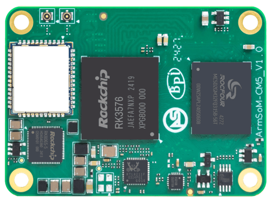
ArmSoM CM5 product photograph.
A custom CM5 carrier should make the product easier to assemble, use and maintain. That means designing around the finished device's connections and service needs, while respecting the module's electrical and software requirements.
Begin with the current ArmSoM CM5 pinout, mechanical drawing and carrier reference resources. Use the exact module revision intended for the product. This checklist helps organize a design review; component values and routing constraints must come from the applicable hardware documentation.
1. Freeze an interface map
List every connector and device on the carrier. For each, record module pins, function, signal voltage, required driver and whether the resource is shared. Resolve multiplexing conflicts before drawing the full schematic.
A product requiring two cameras, a display and several control buses needs a simultaneous-use map, not separate lists of possible functions. Include debug and programming connections so they are not accidentally displaced by another peripheral.
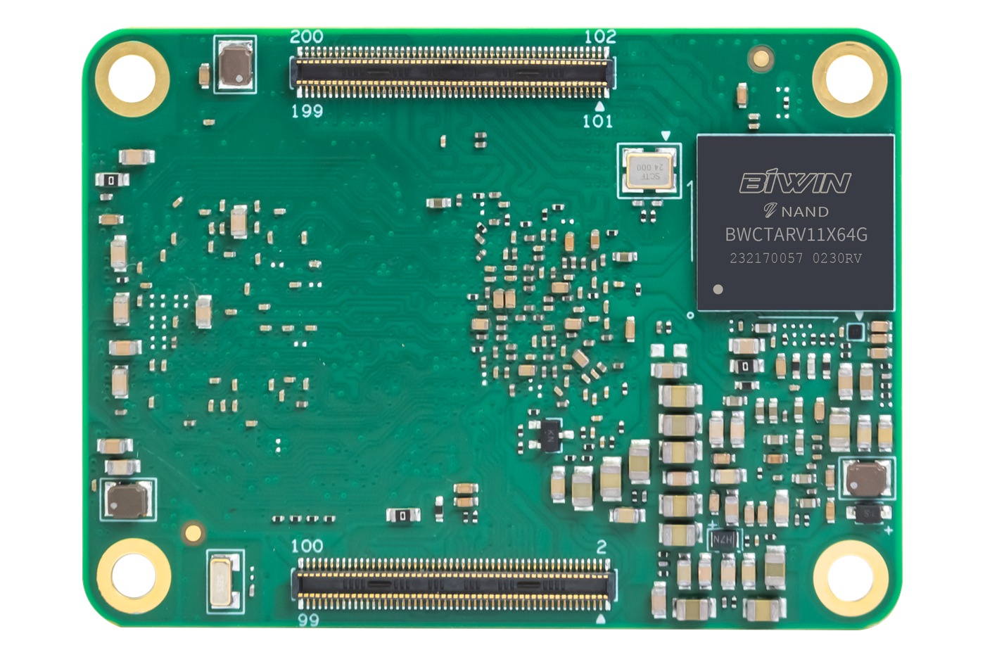
CM5 underside and board-to-board connectors. Use the documented pin assignments and mechanical dimensions when designing the mating carrier. Image: ArmSoM.
2. Design power for startup and load transitions
Build a power tree covering the module, USB devices, display backlight, storage and optional radios. Check startup sequence, enable and reset behavior against the module requirements. Include the load that appears when peripherals initialize together.
Plan protection and power-path behavior at external connectors. Decide how the system responds when a programming cable and normal supply are both connected. Prevent unintended backfeeding and verify what remains powered during shutdown.
Provide measurement access to important rails. A design that exposes power and reset test points is much easier to diagnose during first bring-up than one that hides everything under the module.
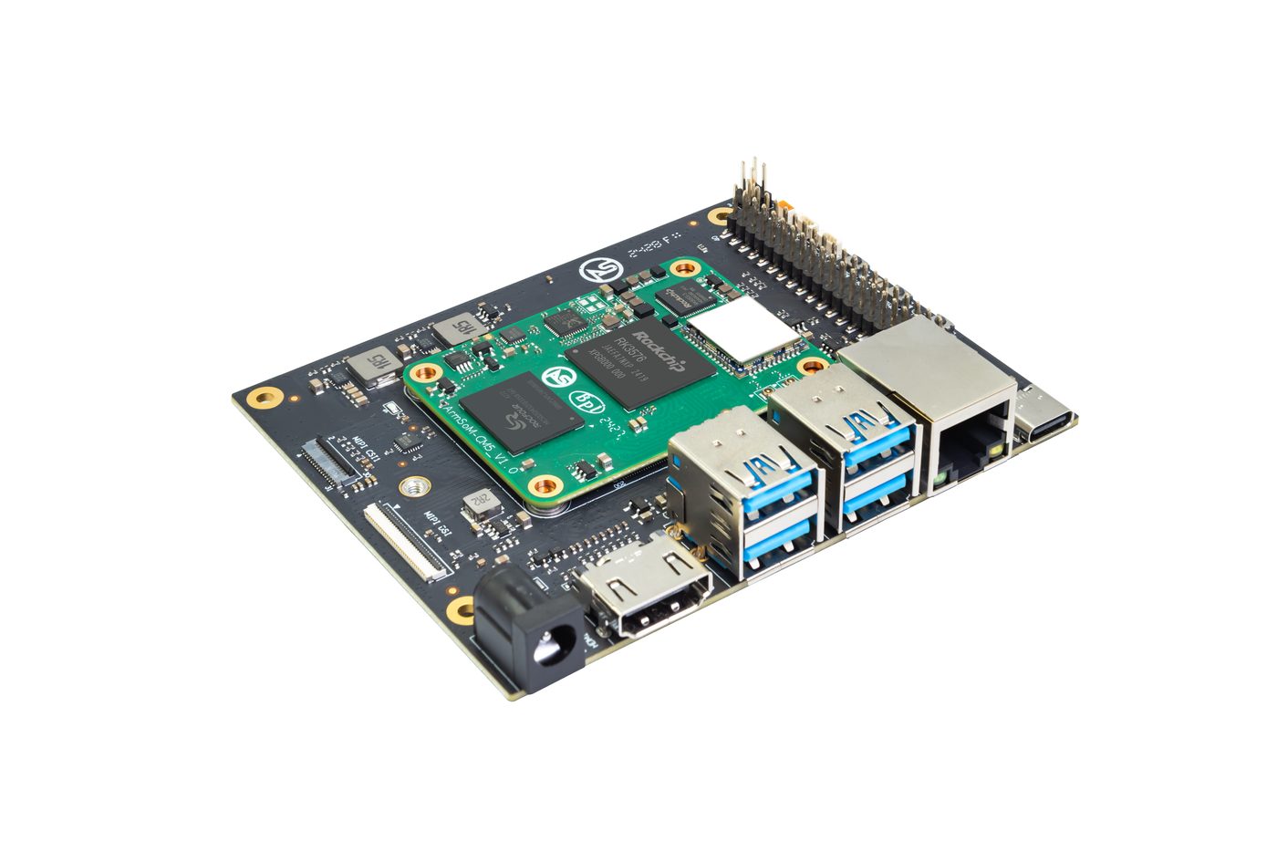
ArmSoM CM5 mounted on a CM5-IO carrier board. This is a board reference photo, not an IMX219 camera installation.
3. Keep programming and recovery accessible
Document the supported boot media and the procedure for entering the module's programming or recovery mode. Make that procedure possible with the finished enclosure, or provide a defined service method.
Route a debug console to an accessible connector or test pads. Label signal levels and ground. The serial console can distinguish a bootloader problem from a kernel or userspace failure before the display and network are working.
4. Review each high-speed interface
Interface | Review focus |
USB | Host/device role, VBUS control, protection and hub behavior |
PCIe | Lane routing, clock, reset, device power and mounting |
Anzeige | Panel timing, lane mapping, control signals and backlight |
Kamera | CSI lanes, clock, I2C, reset and sensor power sequencing |
Ethernet | Module/carrier responsibility, physical-layer circuitry and connector design |
Apply stack-up, impedance, length and reference-plane constraints from the relevant design resources. Review the layout with the actual fabrication stack-up rather than relying only on a generic design-rule preset.
5. Plan the device tree with the schematic
Maintain a table of regulators, GPIOs, bus addresses and peripheral endpoints as the schematic evolves. Use it to prepare the ArmSoM SDK configuration for the carrier. This catches contradictions while changes are still inexpensive.
Keep a hardware revision identifier that software or manufacturing can reliably associate with the correct image. If two revisions need different settings, define the selection method instead of relying on an operator remembering which image to flash.
6. Design for assembly and test
Check connector mating height, module retention, heat-sink mounting and clearance to the enclosure. Consider how the board will be held in a fixture and how connectors will be exercised without excessive wear.
Create an initial factory test list before layout is complete. It should cover programming, identity, power, memory, storage and externally important functions. Add test access where the proposed procedure otherwise has no way to observe a fault.
Sign off the complete integration
Before fabrication, review the schematic, layout, mechanical model and software interface map together. Assign an owner to each unresolved item. After prototypes arrive, validate power and boot before enabling the remaining peripherals one at a time.
Use CM5-IO resources as a reference and discuss project-specific carrier work through ArmSoM's development services. Share the requirement list and drawings early enough for feedback to influence the design.